Motor drive and actuator test automation for robotics and EV drive units
By Alex Hernandez · · 14 min read
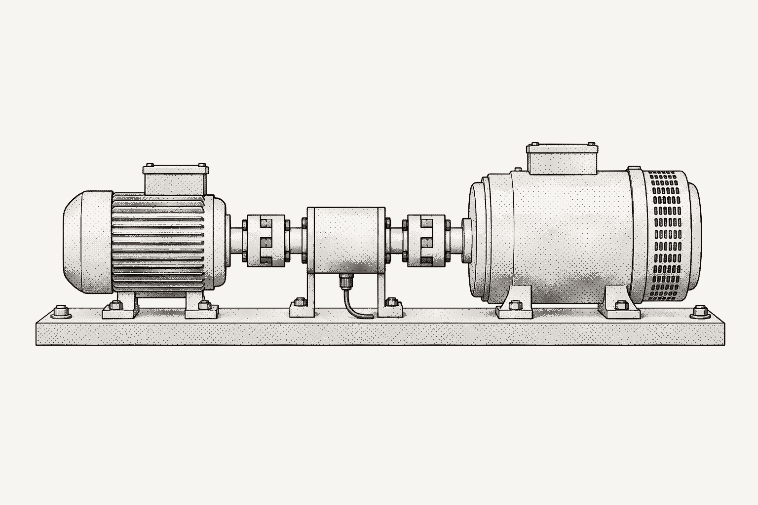
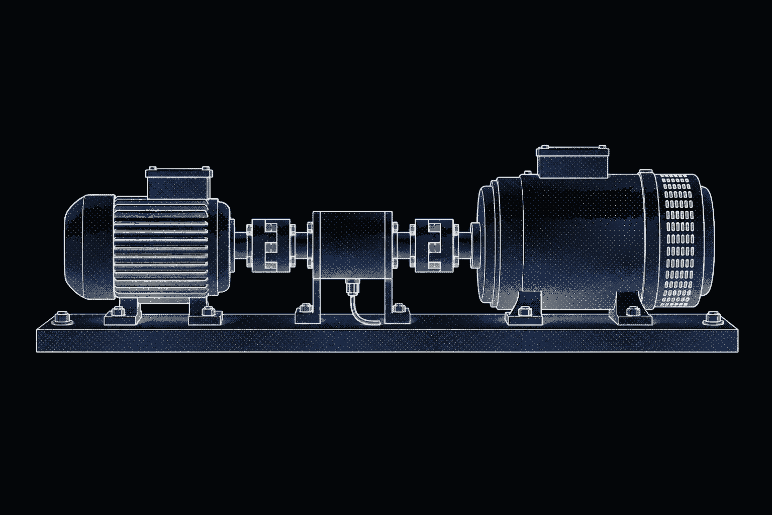
Motor drive test automation means one script or sequence commands the drive over its fieldbus, sets the load on a dynamometer, and reads a power analyzer, torque sensor and temperature channels at every operating point. The checks worth automating are commutation, current-loop response, efficiency, thermal soak, encoder accuracy and drift, and stall and protection behavior.
This guide covers each check for robotic actuators and EV drive units, the drive interfaces, and a Python efficiency-map sketch for a CiA 402 drive and a Yokogawa WT5000. Analyzer details come from Yokogawa's WT5000 Features Guide (IM WT5000-01EN) and Communication Interface manual (IM WT5000-17EN), both 8th edition. General SCPI patterns are in SCPI instrument automation with Python.
What does a motor drive test bench need?
A drive test measures power in three places: the DC bus, the motor phases and the shaft.
| Role | Example equipment | What it gives the test |
|---|---|---|
| DC source | Programmable supply, bidirectional for regeneration tests | Bus voltage, undervoltage ramps |
| Power analyzer | Yokogawa WT5000 with motor evaluation | DC and phase power, efficiency, speed, torque |
| Load | Dynamometer, or a second motor and drive | Holds speed or torque |
| Shaft sensing | In-line torque sensor, encoder on the load shaft | Mechanical power, reference position |
| Waveforms | Oscilloscope with current probes | Phase currents, step response |
| Temperatures | Thermocouple or RTD scanner | Winding, heatsink, coolant |
| Drive under test | Its own telemetry over the fieldbus | State, fault codes, estimated torque and speed |
| Safety | STO circuit, e-stop, guarding | Torque removal that does not depend on software |
The WT5000's motor evaluation option takes analog or pulse signals from a revolution sensor and a torque meter and computes speed, torque, synchronous speed, slip and motor output, Pm = 2π/60 × Speed × Torque × S. With speed in rpm, torque in N·m and the scaling factor S at 1, Pm is in watts, and the analyzer can use it directly in its efficiency equations.
How do robotic actuator and EV drive-unit tests differ?
| Aspect | Robotic joint actuator | EV drive unit |
|---|---|---|
| Assembly | Motor, drive, gearbox and encoders in one joint | Inverter, motor and gearbox, often in one housing |
| DC bus | Low-voltage supply or battery | High-voltage traction battery, with HV interlocks |
| Command interfaces | CANopen (CiA 402), EtherCAT (CoE) or vendor CAN | Vendor CAN messages defined in a DBC file |
| Position feedback | Motor-side encoder, sometimes an output encoder too | Resolver or encoder on the motor |
| Thermal path | Conduction and air | Liquid coolant at a controlled inlet temperature |
| Extra checks | Backlash, torsional stiffness, output torque ripple | Isolation, derating against coolant temperature, regeneration |
An actuator with an output encoder has two position sensors to cross-check. A drive unit stores enough energy in its bus and rotor that protection tests need a written procedure and guarding.
How do you check commutation and the current loop?
Commutation checks confirm the drive knows where the rotor is; current-loop checks confirm it puts the commanded current into the windings.
Back-EMF. With the drive disabled, spin the motor from the load at constant speed and measure the line-to-line voltages. They should match in amplitude and shape, and voltage over speed gives the back-EMF constant to check against the datasheet. Keep peak line-to-line back-EMF below the DC bus voltage, or disconnect the drive; above it, the inverter's freewheeling diodes rectify it into the bus.
Hall sequence. With sensors 120 electrical degrees apart, a slow rotation produces six valid states per electrical revolution. All-zeros and all-ones never occur, so either one means a wiring or sensor fault.
Encoder offset. With the encoder's A, B and Z channels on its motor input, the WT5000 reports the phase of each voltage and current fundamental relative to the rising edge of the Z pulse. Back-drive the motor with the drive disabled, and the voltage angle is the index-to-back-EMF offset. Convert it to the drive's commutation convention before comparing: back-EMF leads rotor flux by 90 electrical degrees, and line-to-line voltage differs from phase voltage by 30. The WT5000 disables this measurement at a 10 ms update interval.
Current-loop step response. Hold the shaft at zero speed with the load, step the torque command over the fieldbus, and capture phase current on the oscilloscope. Compare rise time, overshoot and settling with the specification. Repeat at minimum and maximum bus voltage and after a thermal soak, since winding resistance rises with temperature.
Zero-current offset. Enable with zero torque and measure phase currents; a sensor offset shows up as torque ripple at the electrical frequency.
Throughout, treat drive telemetry as an estimate and the instruments as the reference.
How do you measure motor drive efficiency?
Wire one analyzer element to the DC bus, two or three elements to the motor phases as a wiring unit (Yokogawa's ΣA, ΣB or ΣC), and the torque and speed signals to the motor input. Three efficiencies follow: inverter (motor-terminal power over DC power), motor (Pm over motor-terminal power) and drive unit (Pm over DC power). On the WT5000, :MEASure:EFFiciency:ETA<x> takes a numerator and then a denominator from element powers (P1 to P7), wiring-unit powers (PA, PB, PC) and motor outputs (PM1 to PM4).
An efficiency map repeats that measurement over a grid of speeds and torques. Four rules keep it repeatable:
- Settle, then read fresh data. The WT5000 returns whatever it currently holds, so wait for the end of a data update after the point settles. Yokogawa WT power analyzer automation covers this and fixed ranging.
- Record temperatures with every point. Copper losses move with winding temperature.
- Handle the generating quadrants. When the load drives the motor, power flows from shaft to bus and the motoring formula reads above 100 percent. Define those points as electrical output over mechanical input.
- Log the ranges. The analyzer's voltage, current, speed and torque ranges are numeric items like any other.
How do you run a thermal soak on a motor drive?
A thermal soak runs the drive at a continuous rating until temperatures stop changing, then checks torque, temperature limits and derating against the datasheet. The stop condition is a slope, not a duration, and it goes into the test plan before the run:
import numpy as np


def settled(t_s, temp_c, window_s=1800.0, max_k_per_h=1.0) -> bool:
    """True when the temperature slope over the last window is under the plan's limit."""
    t, y = np.asarray(t_s, float), np.asarray(temp_c, float)
    if t[-1] - t[0] < window_s:
        return False
    recent = t >= t[-1] - window_s
    slope_k_per_s = np.polyfit(t[recent], y[recent], 1)[0]
    return abs(slope_k_per_s) * 3600 <= max_k_per_h
Apply it to the winding, the heatsink or the drive's reported power-stage temperature, the gearbox, and coolant in and out; the window and slope above are placeholders for your plan's values. Log the drive's current limit and fault state alongside, so a derating step sits next to the temperature that caused it. Peak-torque tests use a timed limit instead: hold peak torque for its rated duration and compare the drive's overload response with its documentation.
How do you test encoder accuracy and drift?
Encoder tests compare the drive's position with a better reference on the same shaft.
- Accuracy. Rotate slowly and record the drive's position actual value against a reference encoder. Error that repeats once per revolution usually points to mounting eccentricity; error that repeats many times per revolution points to the encoder itself.
- Count integrity. After many revolutions in each direction, the count at the index pulse should return to the same value. Counts lost only at high current point to noise from the PWM stage.
- Drift. Repeat the accuracy run after the thermal soak. An offset that moves with temperature also moves commutation, so rerun the electrical-angle check.
- Two-encoder actuators. Compare motor-side position divided by the gear ratio with the output encoder. Direction reversals at light load show backlash; torque against a locked output shows torsional windup.
How do you test stall and protection behavior?
Protection tests provoke each fault on purpose and check that the drive detects it, reacts as documented and reports a fault code you can read back. Run them last, under a written procedure, with guarding and hardwired safety in place.
| Protection | How to provoke it | What to record |
|---|---|---|
| Stall | Hold zero speed, command torque | Current limit, time to derate or trip |
| Overload | Hold peak torque past its rated duration | Derating against the drive's overload curve |
| Bus overvoltage | Decelerate a high-inertia load | Peak bus voltage, brake chopper or fault |
| Bus undervoltage | Ramp the DC source down under load | Threshold, clean shutdown, restart behavior |
| Overtemperature | Extend the soak or raise coolant temperature | Derating steps, trip temperature |
| Feedback loss | Disconnect the encoder or resolver at low speed | Detection time, fault reaction |
| Communication loss | Stop the heartbeat or disconnect the bus | Configured reaction and its timing |
| Safe Torque Off | Assert the STO input while running | Torque removal, statusword, what re-enable requires |
A unidirectional bench supply cannot absorb regenerated energy, so deceleration pumps up the bus: the point of the overvoltage test and a hazard in every other one. For STO, SEW-Eurodrive describes the IEC 61800-5-2 function as the inverter no longer supplying torque-producing power, a stop category 0 in EN 60204-1. The shaft coasts unless something holds it.
After each test, read the statusword and error code before resetting anything; an automatic reset erases the evidence.
Which interfaces do motor drives use for test automation?
CANopen with CiA 402. CiA 402 is the CANopen device profile for servo drives, frequency inverters and stepper motor controllers. Parts of it are standardized as IEC 61800-7-201 and IEC 61800-7-301, and the February 2024 revisions add 64-bit position values. Compliant drives share one state machine, so state handling carries across vendors; units and optional objects still differ. Indexes below are from Synapticon's CiA 402 object dictionary and the python-canopen 402 code:
| Object | Name | Use in tests |
|---|---|---|
| 0x6040 | Controlword | State transitions, quick stop |
| 0x6041 | Statusword | Current state of the drive state machine |
| 0x603F | Error code | Fault cause after a trip |
| 0x6060, 0x6061 | Modes of operation, and its display | Select and confirm the mode |
| 0x6071, 0x60FF, 0x607A | Target torque, velocity, position | Steps and operating points |
| 0x6077, 0x606C, 0x6064 | Torque, velocity, position actual value | Compare with the instruments |
| 0x6079 | DC link circuit voltage | Bus voltage during regeneration tests |
Velocity and torque objects may be scaled, so read the drive's scaling first. SDO reads suit settled points; for fast tests, map the statusword and actual values into TPDOs. EtherCAT drives that implement CANopen over EtherCAT (CoE) carry the same objects, as Synapticon's documentation shows.
Modbus RTU and TCP. For drives that expose a register map, the Modbus application protocol specification defines register functions including 03 Read Holding Registers, 04 Read Input Registers, 06 Write Single Register and 16 Write Multiple Registers, with up to 125 registers per read. Three details trip up scripts. The data model numbers registers 1 to 16 but the wire addresses them 0 to 15; check which the drive's manual lists. Each register is 16 bits, most significant byte first. And the specification says nothing about 32-bit values, so the word order of a 32-bit speed or position is in the drive's manual.
Vendor CAN. Drives commanded with vendor-specific CAN messages document them as message IDs and signal layouts, usually in a DBC file. Decode with the DBC, not hand-written bit masks; BMS validation testing shows how.
What does an automated motor drive test sequence look like?
Order the campaign so each stage establishes what the next needs, and risky tests come last.
| Stage | Steps | Gate before the next stage |
|---|---|---|
| 1. Identity | Firmware, parameters, instrument IDs | Matches the plan |
| 2. Commutation | Back-EMF, hall sequence, encoder offset | Offset within tolerance |
| 3. Current loop | Zero-current offset, torque steps | Within specification |
| 4. Efficiency map | Speed and torque grid | Every point settled |
| 5. Thermal soak | Continuous rating to equilibrium | No unplanned derating |
| 6. Encoder | Accuracy and counts, cold and hot | Within limits |
| 7. Protection | One fault at a time | Reactions as documented |
The sketch below is stage 4, using python-canopen (MIT license) for a CiA 402 drive on SocketCAN and PyVISA for a WT5000 with the /MTR1 option. Element 1 measures the DC bus, elements 2 and 3 form wiring unit ΣA on the motor phases, and Motor1 takes torque and speed. The dynamometer holds speed while the drive produces torque.
import json
import math
import statistics
import time

import canopen
import pyvisa
from canopen.profiles.p402 import BaseNode402

SPEEDS_RPM = [500, 1000, 2000, 3000]  # keep line-to-line back-EMF below the bus
TORQUES = [100, 250, 500, 750]  # 0x6071 target torque, in the drive's units
SETTLE_S = 5.0
READS_PER_POINT = 8
ITEMS = {  # WT5000 numeric items, in output order
    "p_dc_w": "P,1", "p_motor_w": "P,SIGMA", "speed_rpm": "SPEed,1",
    "torque_nm": "TORQue,1", "pm_w": "PM,1",
    "eta_inverter": "ETA1", "eta_motor": "ETA2", "eta_unit": "ETA3",
}


def dyno_hold_speed(rpm: float) -> None:
    raise NotImplementedError("call your dynamometer controller here")


def open_drive(node_id: int, eds: str) -> tuple[canopen.Network, BaseNode402]:
    network = canopen.Network()
    network.connect(interface="socketcan", channel="can0")  # bitrate is set with `ip link`
    drive = BaseNode402(node_id, eds)
    network.add_node(drive)
    drive.nmt.state = "PRE-OPERATIONAL"
    drive.setup_402_state_machine()  # reads the drive's PDO mapping over SDO
    drive.nmt.state = "OPERATIONAL"
    drive.op_mode = "PROFILED TORQUE"  # raises TypeError if the drive lacks the mode
    drive.sdo[0x6071].raw = 0
    return network, drive


def open_analyzer(rm: pyvisa.ResourceManager, resource: str):
    wt = rm.open_resource(resource, timeout=10_000)
    wt.write(":MEASure:EFFiciency:ETA1 PA,P1")   # inverter: P(ΣA) / P1
    wt.write(":MEASure:EFFiciency:ETA2 PM1,PA")  # motor: Pm1 / P(ΣA)
    wt.write(":MEASure:EFFiciency:ETA3 PM1,P1")  # drive unit: Pm1 / P1
    for n, item in enumerate(ITEMS.values(), start=1):
        wt.write(f":NUMeric:NORMal:ITEM{n} {item}")
    wt.write(f":NUMeric:NORMal:NUMber {len(ITEMS)}")
    wt.write(":NUMeric:FORMat ASCii")
    wt.write(":STATus:FILTer1 FALL")  # set an event bit when each data update ends
    wt.query(":STATus:EESR?")         # reading the register clears it
    return wt


def read_fresh(wt) -> dict[str, float]:
    wt.write(":COMMunicate:WAIT 1")  # the next command waits for the end of an update
    values = wt.query_ascii_values(":NUMeric:NORMal:VALue?")
    wt.query(":STATus:EESR?")
    return dict(zip(ITEMS, values))


def telemetry(drive: BaseNode402) -> dict[str, int]:
    return {
        "statusword": drive.sdo[0x6041].raw,
        "error_code": drive.sdo[0x603F].raw,
        "drive_velocity": drive.sdo[0x606C].raw,  # drive units
        "drive_torque": drive.sdo[0x6077].raw,    # drive units
        "dc_link": drive.sdo[0x6079].raw,         # if the drive's EDS defines it
    }


def run_map(drive: BaseNode402, wt, log) -> None:
    drive.state = "OPERATION ENABLED"  # python-canopen allows 0.8 s by default
    try:
        for rpm in SPEEDS_RPM:
            dyno_hold_speed(rpm)
            for torque in TORQUES:
                drive.sdo[0x6071].raw = torque
                time.sleep(SETTLE_S)
                if drive.state != "OPERATION ENABLED":
                    raise RuntimeError(f"drive left OPERATION ENABLED: {telemetry(drive)}")
                reads = [read_fresh(wt) for _ in range(READS_PER_POINT)]
                if not all(math.isfinite(v) for r in reads for v in r.values()):
                    raise RuntimeError(f"no data or over-range at {rpm} rpm, torque {torque}")
                point = {k: statistics.fmean(r[k] for r in reads) for k in ITEMS}
                record = {"t": time.time(), "rpm_set": rpm, "torque_set": torque,
                          **point, **telemetry(drive)}
                log.write(json.dumps(record) + "\n")
    finally:
        drive.sdo[0x6071].raw = 0
        if drive.state not in ("FAULT", "FAULT REACTION ACTIVE"):  # keep faults for diagnosis
            drive.state = "SWITCH ON DISABLED"  # torque off; the dynamometer still turns the shaft


if __name__ == "__main__":
    rm = pyvisa.ResourceManager()
    wt = open_analyzer(rm, "TCPIP0::192.168.1.60::inst0::INSTR")
    network, drive = open_drive(node_id=1, eds="drive.eds")
    try:
        with open("efficiency_map.jsonl", "a") as log:
            run_map(drive, wt, log)
    finally:
        network.disconnect()
        wt.close()
Four details carry over to every stage:
- State handling. python-canopen's
statesetter walks the CiA 402 transitions and raisesRuntimeErrorwhen the drive does not reach the target state in time (TIMEOUT_SWITCH_STATE_SINGLEandTIMEOUT_SWITCH_STATE_FINAL, 0.4 and 0.8 seconds by default). Raise them for drives that precharge on enable. - Fresh data.
:STATus:FILTer1 FALLwith:COMMunicate:WAIT 1is the WT5000 manual's own pattern for waiting on the end of a data update. - Faults stay visible. In python-canopen, commanding SWITCH ON DISABLED from FAULT sends the fault-reset controlword, so the
finallyblock skips it. - Software is not the interlock. STO, the e-stop and the dynamometer's limits act when the script does not.
How do I run a motor drive efficiency map in Galois with Évariste?
Évariste, the agent in the Galois platform, runs the same stage 4 map on the bench through the galois-edge daemon; open it from the app sidebar (Ctrl+Shift+E).
-
Find the instruments. "List connected instruments" shows the WT5000 and the rest of the bench across your team's edges. If the dynamometer controller has no profile yet, upload its programming manual; Évariste generates a profile and, after you review it, deploys it to the edge and binds it to the instrument. The drive's CAN messages come from a
dbc2galoisprofile built from a DBC file of its PDOs; see below. Check that enable and torque commands carry theis_dangerousflag. -
State the objective and limits from your plan and datasheets:
Map efficiency on the drive at node 1 with the WT5000 and the dynamometer. Element 1 is the DC bus, elements 2 and 3 form ΣA on the motor phases, Motor1 takes torque and speed. Define ETA1 as PA over P1, ETA2 as PM1 over PA, ETA3 as PM1 over P1. In profiled torque mode, hold the dyno at 500, 1000, 2000 and 3000 rpm and step target torque through 100, 250, 500 and 750 drive units. At each point wait 5 s, confirm OPERATION ENABLED, average eight fresh updates of P1, PΣA, speed, torque, Pm1 and ETA1 to ETA3, and log statusword, error code, drive velocity, torque and DC link. Fail any NAN or INF. Finish at zero torque with the drive disabled; never reset a fault.
-
Review the draft. Évariste returns a draft sequence: setup steps for the efficiency equations, item list and update filter, an enable step, a sixteen-point loop with waits, reads and limits, then zero-torque and disable steps. It does not run until you approve it. Check for
:STATus:FILTer1 FALLin setup,:COMMunicate:WAIT 1before each read, the state check before the reads and no fault-reset controlword; decide what follows a failed point, where the script stops and zeroes torque; and confirm peak line-to-line back-EMF at 3000 rpm stays below the bus. Edit in conversation or the sequence builder; every change is a new version with a diff, and a settled sequence can be production-locked. -
Run it. Wire the analyzer, confirm STO, the e-stop, the dynamometer's limits and guarding, and start the run with the drive's serial. galois-edge executes each step while Monitor shows the channels live; dangerous commands sent by hand wait for your confirmation.
-
Read the results. Each step records its measured value, limits, pass/fail, raw command and response, instrument, operator, DUT serial and timestamps. Ask Évariste which points failed and what the drive reported there, or to compare this map with one taken after the thermal soak; answers cite the runs.
-
Report. "Generate a test report from the last run" builds a PDF or HTML report from a LaTeX template. In the report editor, add the drive and dyno serials, the STO and e-stop check, and whether the map was taken before or after the thermal soak, then share it to Slack.
| Step | Code path (this guide) | Galois with Évariste |
|---|---|---|
| Connect | open_analyzer(), open_drive() | galois-edge discovery, bound profiles |
| Drivers | python-canopen, PyVISA, dyno_hold_speed() | Library and generated profiles |
| Analyzer setup | ETA<x> equations, ITEMS | Draft setup steps |
| Sweep | run_map() loops, SETTLE_S | Loop and wait steps |
| Fresh data | read_fresh() | :COMMunicate:WAIT 1 before each read |
| Checks | math.isfinite(), drive state | Limit steps you approve |
| Shutdown | finally block, faults kept | Zero-torque and disable steps, no fault reset |
| Record | efficiency_map.jsonl | Per-step run record |
| Interpret | Your own analysis | Failed points, run comparisons |
| Report | Your own script | "Generate a test report from the last run" |
You no longer write or maintain the CANopen and VISA session code, the dynamometer call, the sweep loop, the state and range checks, the JSONL logging or a report script. The objective, datasheet limits, review, approval, wiring, STO and guarding stay yours. The other stages follow the same flow; AI test automation for hardware benches explains the draft-and-approve model.
Where Galois fits
Galois is agent-driven test engineering for hardware teams: agents generate tests and instrument drivers, run them on real benches through the open-source galois-edge daemon, and turn the results into reports and a shared engineering record.
On a drive bench, the daemon discovers instruments over GPIB, USB, LAN and serial, connects Modbus TCP and RTU devices from profiles that describe their register maps, and drives CAN devices through python-can from profiles that declare messages and signals. Its dbc2galois script turns a vendor DBC file into such a profile. Galois ships 573 instrument profiles across 135 manufacturers (instrument library), including power analyzers such as the Yokogawa WT5000, Tektronix PA4000 and ZES Zimmer LMG670, and the Magtrol TS102 torque sensor. For a dynamometer controller outside the library, Évariste drafts a profile from its programming manual for an engineer to review, as the walkthrough above shows; declarative instrument drivers explains the format.
Galois sequences gate execution on approval: a draft cannot run until an engineer approves it, and an edited sequence needs approval again. When Évariste drafts a drive campaign, the engineer checks its limits and abort conditions first; see reviewing an AI-generated test plan and LLM instrument safety. EVT, DVT and PVT testing places drive tests in a build schedule.
Frequently asked questions
- What is CiA 402?
- CiA 402 is the CANopen device profile for drives and motion control. It standardizes how servo drives, frequency inverters and stepper motor controllers behave: a state machine commanded through the controlword (0x6040) and reported in the statusword (0x6041), operation modes such as profiled torque, velocity and position, and objects for target and actual values. Parts of it are also published as IEC 61800-7-201 and IEC 61800-7-301.
- How do you measure the efficiency of a motor and drive?
- Measure electrical power on the DC bus, electrical power at the motor terminals, and mechanical output from a torque sensor and a speed signal. Mechanical power in watts is 2π/60 times speed in rpm times torque in N·m. Inverter efficiency is motor-terminal power over DC power, motor efficiency is mechanical power over motor-terminal power, and drive-unit efficiency is mechanical power over DC power. Record each point only after speed, torque and temperature have settled.
- Can I run a motor drive efficiency map without writing Python?
- Yes. Give Évariste, the agent in the Galois platform, the map in plain English with your wiring, points and limits, such as WT5000 element 1 on the DC bus, ΣA on the motor phases, the dynamometer held at four speeds from 500 to 3000 rpm, target torque stepped through four points and a failure on any NAN or INF reading, and it drafts a versioned sequence; if the dynamometer controller has no profile, it generates one from the programming manual you upload. You review the profile and approve the sequence before it runs on the bench through galois-edge with the drive's serial, and Évariste finds the failed points, compares runs and generates the test report. Wiring, STO and guarding stay yours.
- What is Safe Torque Off (STO)?
- Safe Torque Off is a drive safety function defined in IEC 61800-5-2: while it is active, the drive no longer supplies torque-producing power to the motor. It is an uncontrolled stop, stop category 0 in EN 60204-1, so the shaft coasts unless a brake or the load holds it. On a test bench, STO is wired into hardware safety circuits; automated tests verify it and never stand in for it.
- How long should a motor drive thermal soak run?
- Until temperatures stop changing, not for a fixed time. Write the stability criterion into the test plan, such as a maximum slope in kelvin per hour over a fixed window for the winding, heatsink and coolant channels, and let the sequence check it. A fixed duration either ends before equilibrium or spends bench time after it.
Bring Galois to your bench.
The daemon is Apache-2.0, free forever. Enterprise runs in your cloud or on-prem.