Board bring-up checklist: from first power-on to a repeatable sequence
By Alex Hernandez · · 14 min read
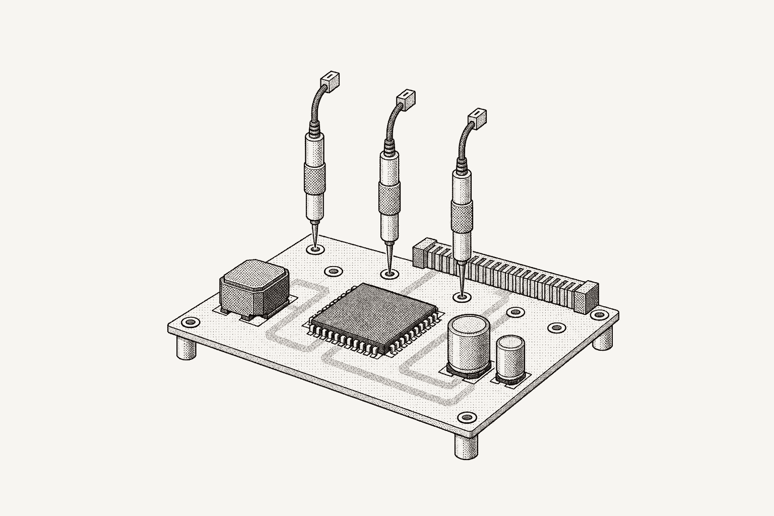
A board bring-up checklist takes a new PCB from assembled to trusted in a fixed order: inspect it unpowered, measure each rail's impedance to ground, apply current-limited power, verify rail voltage, sequencing and ripple, confirm clocks and resets, connect the debugger, then bring up peripherals one bus at a time. Each step assumes the one before it passed.
The order is the point. A shorted rail makes every later measurement meaningless, and a debugger that will not connect is often a clock or reset problem. Write every value down: the first board's numbers become the reference for the second, and the checklist becomes the specification for a sequence that runs on every board after it.
What does a board bring-up checklist cover?
Eight stages, in order. The last column is the evidence to keep for each board; an automated sequence compares against it later.
| Stage | What you check | Instruments | Record per board |
|---|---|---|---|
| 1. Inspection | Part orientation, solder bridges, parts against the BOM, straps | Microscope | Photos, rework notes |
| 2. Unpowered impedance | Each rail to ground and to adjacent rails | DMM | Ohms per rail, both polarities |
| 3. First power | Input current under a limit and an overcurrent trip | Bench supply | Current per voltage step, supply mode |
| 4. Rails | Voltage at the load, order, ramp shape, ripple, heat | DMM, oscilloscope, thermal camera | Volts, delays, ripple with bandwidth |
| 5. Clocks and resets | Frequency, reset release, strap levels | Oscilloscope or counter | Frequency, reset delay |
| 6. Debug access | JTAG or SWD, IDCODE, program and verify | Debug probe, OpenOCD | IDCODE, image hash |
| 7. Peripherals | UART, I2C and SPI devices, then high-speed links | Oscilloscope, logic analyzer | Address map, ID registers |
| 8. Automation | Which checks become a sequence | All of the above | Sequence version, limits |
What to check before applying power
Visual inspection. Check every polarized part: diodes, electrolytic and tantalum capacitors, and the pin-1 mark on each IC and connector. Look for solder bridges on fine-pitch pins, tombstoned passives, and parts missing, rotated or fitted where the BOM says do-not-populate. Ball-grid packages need the assembler's X-ray images. Confirm jumpers and boot-mode straps against the schematic; a wrong strap looks like a dead processor.
Rail impedance. Measure resistance from each rail to ground with a DMM, then swap the leads and measure again; semiconductor junctions on the rail make the two readings differ. The reading drifts upward as the meter charges the bulk capacitance; note it once it settles. A reading near zero ohms is a short: find it before anything is powered. Measure between adjacent rails too, since a bridge between 3.3 V and 1.8 V never shows up as a short to ground.
The best reference is another board: the same rail on two boards from one batch should read alike, and one that reads far lower than its siblings deserves attention even when it is not a dead short. Keep the readings in a table keyed by rail and board serial.
How to power a new board for the first time
Use a bench supply with a current limit, not the board's eventual power source. Set the voltage to the nominal input, and set the current limit a modest margin above the idle current the power budget predicts. If the board has a short, the supply drops into constant-current mode and holds the current at the limit instead of delivering whatever the fault will draw. Overcurrent protection (OCP) adds a backstop that turns the output off.
Ramp the input voltage in steps rather than switching straight to nominal, and watch the current at each step: current that climbs before the regulators should be running points at a fault while less energy is available to do damage. Check the datasheets first: an LDO output follows a slow input ramp, and some processors and FPGAs specify a maximum rail ramp time. If zero-ohm links, jumpers or enable pins let you isolate rails, bring them up one at a time.
The procedure is mechanical enough to script from the first board. This version drives a Rigol DP800-series supply over PyVISA with commands from the DP800 programming guide. :OUTPut:MODE? returns CV, CC or UR, the unregulated boundary between the two, and :OUTPut:OCP:QUES? reports whether overcurrent protection fired.
import time

import pyvisa

RESOURCE = "TCPIP0::192.168.1.60::INSTR"  # the supply's VISA address
CH = "CH1"        # DP832 CH1: 0 to 32 V, 0 to 3.2 A
V_INPUT = 12.0    # nominal board input, V
I_CLAMP = 0.25    # constant-current limit, A
I_TRIP = 0.20     # OCP: the output turns off above this, A
STEPS = 12        # ramp from 0 to V_INPUT in equal steps
DWELL_S = 0.5     # let the board settle at each step

rm = pyvisa.ResourceManager()
psu = rm.open_resource(RESOURCE, read_termination="\n", write_termination="\n", timeout=5_000)
print(psu.query("*IDN?").strip())

psu.write(f":OUTP {CH},OFF")
psu.write(f":OUTP:OCP:CLEAR {CH}")
psu.write(f":APPL {CH},0,{I_CLAMP}")
psu.write(f":OUTP:OCP:VAL {CH},{I_TRIP}")
psu.write(f":OUTP:OCP {CH},ON")
psu.write(f":OUTP {CH},ON")

try:
    for n in range(1, STEPS + 1):
        v_set = V_INPUT * n / STEPS
        psu.write(f":APPL {CH},{v_set:.3f},{I_CLAMP}")
        time.sleep(DWELL_S)
        tripped = psu.query(f":OUTP:OCP:QUES? {CH}").strip() == "YES"
        mode = psu.query(f":OUTP:MODE? {CH}").strip()
        volts, amps, _watts = (float(x) for x in psu.query(f":MEAS:ALL? {CH}").split(","))
        print(f"{v_set:6.2f} V set  {volts:6.3f} V  {amps * 1e3:7.1f} mA  {mode}")
        if tripped or mode != "CV":
            reason = "OCP tripped" if tripped else f"supply in {mode} mode"
            raise RuntimeError(f"stopped at {v_set:.2f} V: {reason}")
except BaseException:  # includes Ctrl-C (KeyboardInterrupt)
    psu.write(f":OUTP {CH},OFF")  # safe state: output off
    raise
The trip sits below the clamp on purpose: above the OCP value the DP800 turns the output off, and the clamp bounds the current until it does. Any mode other than CV, an error or Ctrl-C stops the script with the output off. The time.sleep() is a dwell for the board, not instrument synchronization; the SCPI automation guide covers *OPC? and error queues.
At nominal input, give the board a few minutes and look for hot parts with a thermal camera or thermocouple. A regulator that heats up at idle is a fault even when every voltage reads correctly.
How to verify power rail voltage, sequencing and ripple
Voltage at the load. Measure each rail at a decoupling capacitor next to the IC it feeds, not only at the regulator output, and compare against that IC's datasheet tolerance rather than the regulator's setpoint.
Sequencing. Many FPGAs, SoCs and processors specify the order their rails come up, the delays between them, and a monotonic ramp. Put the input rail, regulator outputs and main reset on the oscilloscope, trigger single-shot on the input's rising edge, and capture power-up. Check order and delays against the datasheets, look for plateaus or dips, and confirm reset releases after the last rail settles. Then capture power-down, which bring-up often skips.
Ripple. Probe at the output capacitor's terminals with a ground spring, not the probe's ground lead. Texas Instruments' application note SLVAF30 shows why: the loop between probe tip and ground must be as small as possible to avoid noise coupling. In its boost-converter example, a high-frequency spike sits on top of the switching ripple, mainly from the output capacitor's equivalent series inductance, and it looks much smaller at a 20 MHz bandwidth setting because the scope then acts as a low-pass filter. Record the bandwidth next to every ripple number.
Measure under load as well as at idle, with an electronic load or firmware that exercises the board. The power rail validation plan covers load steps, margining and limits, and DC-DC converter validation covers ripple against the design calculation and the regulators themselves.
How to check clocks and resets on a new board
Resets. The sequencing capture already shows when reset releases relative to the rails. Confirm the supervisor's threshold and delay against its datasheet, check that the reset button and the debug header's reset pin reach the same net, and confirm boot-mode straps sit at their intended levels while reset is asserted, since processors commonly sample them as it releases.
Clocks. Probe powered oscillators at their outputs and measure frequency and amplitude with the oscilloscope or a counter. Crystals are different. Microchip's application note AN2648 warns against probing a crystal directly: standard 10X oscilloscope probes impose a loading of 10 to 15 pF, and touching the crystal pins with a finger or a 10X probe can start or stop oscillation or give false results. Measure the clock where it is buffered: AN2648 supplies firmware that outputs it, divided down, on an I/O pin, which a 10X probe can load without affecting the measurement.
That needs firmware, so clock checks often finish after the debugger connects; then read the PLL lock status too. A processor still running from an internal oscillator because the external one never started can look healthy while every derived timing is wrong.
How to bring up JTAG and SWD debug access
Check the debug header first: pin-1 orientation, the target voltage reference pin, and the pull-ups the processor datasheet asks for. Then start slow. The OpenOCD manual advises an initial JTAG clock slow enough that OpenOCD never starts faster than the scan chain supports, and notes that most Arm cores accept at most one sixth of the CPU clock, which is low before the PLL is configured.
Read the IDCODE first. With no TAPs declared, OpenOCD autoprobes the chain: after a JTAG reset each TAP holds its IDCODE or BYPASS register, and if communication works OpenOCD reports each TAP and the -expected-id to use. Compare it with the datasheet or BSDL file. No response, or an IDCODE of all ones or all zeros, usually means an open or stuck signal, a held reset or a missing clock, so go back a step before replacing cables.
Many Arm parts expose SWD instead of, or alongside, JTAG; the OpenOCD manual describes it as an Arm-specific, debug-oriented transport that uses fewer signal wires and does not support boundary scan. The same rule applies: connect slowly, identify the part, then program.
Then program a minimal image: a console UART message, a toggled GPIO, and the clock routed to a pin for the previous step. Verify flash after writing and record the image hash with the board serial.
How to bring up peripherals one bus at a time
Bring up the console UART first, since every later check reports through it. Then go bus by bus and confirm each device answers before writing any driver beyond a register read.
I2C. Look at SDA and SCL on the oscilloscope before scanning. The I2C-bus specification, NXP UM10204, limits rise time, measured from 30% to 70% of VDD, to 1,000 ns in Standard-mode, 300 ns in Fast-mode and 120 ns in Fast-mode Plus. The specification gives the largest usable pull-up as Rp(max) = tr / (0.8473 × Cb), so slow edges mean a pull-up too weak for the bus capacitance, or a missing one.
Then scan. On a Linux host, i2cdetect probes addresses 0x08 to 0x77 by default and prints each address that answered, -- where nothing answered, and UU where a kernel driver already claims the address. Its manual page warns that probing can confuse an I2C bus and cause data loss, so scan once and compare against the address map from the schematic:
import re
import subprocess

# Expected 7-bit addresses on bus 1, from the schematic (designators are examples)
EXPECTED = {0x48: "U7 temperature sensor", 0x50: "U12 EEPROM", 0x6B: "U3 charger"}


def scan(bus: int) -> tuple[set[int], set[int]]:
    """Addresses that acknowledged an i2cdetect probe, and addresses shown as UU (claimed by a driver, not probed)."""
    table = subprocess.run(
        ["i2cdetect", "-y", str(bus)], capture_output=True, text=True, check=True
    ).stdout
    found: set[int] = set()
    claimed: set[int] = set()
    for row in table.splitlines()[1:]:  # skip the column header
        base, _, cells = row.partition(":")
        for col in range(16):  # each cell is three characters wide: a space and two
            cell = cells[3 * col + 1 : 3 * col + 3]
            addr = int(base, 16) + col
            if cell == "UU":
                claimed.add(addr)
            elif re.fullmatch(r"[0-9a-f]{2}", cell):
                found.add(addr)
    return found, claimed


found, claimed = scan(1)
missing = sorted(f"0x{a:02x} {name}" for a, name in EXPECTED.items() if a not in found | claimed)
unexpected = sorted(f"0x{a:02x}" for a in found - set(EXPECTED))
print("missing:", missing or "none")
print("unexpected:", unexpected or "none")
print("claimed by a driver, check separately:", sorted(f"0x{a:02x}" for a in claimed) or "none")
-y skips the interactive confirmation; the manual page says the flag is mainly meant for scripts. A missing address usually means a strap that differs from the schematic, an unpowered device or a solder fault; then read an identification register from each device that answered.
SPI and the rest. Read an identification register from each SPI device at a low clock rate first. Leave memory, PCIe, Ethernet and USB for last: they depend on everything above, and their vendor tools for training and link status deserve their own checklist.
Which bring-up steps should you automate on the next board?
The first board is where the checklist gets written. From the second on, most of it can run as a sequence, and the gain is consistency: the same steps, order and limits, with the record kept every time. A good candidate has a fixed connection to the board and a numeric result.
| Step | Automate? | What it needs |
|---|---|---|
| Visual inspection | No | An engineer, or optical inspection at the assembler |
| Rail impedance | When test points are fixed | DMM plus a switch matrix or fixture |
| Current-limited power-up | Yes | Bench supply and the script above |
| Rail voltages at the load | Yes | DMM through a switch matrix |
| Sequencing and ripple | Yes | Oscilloscope with a saved setup and automated measurements |
| Clock frequency | Yes, once firmware routes it to a pin | Counter or oscilloscope |
| IDCODE and programming | Yes | OpenOCD or a vendor command-line programmer |
| Peripheral presence | Yes | Console script, I2C scan against the expected map |
| Thermal check | Partly | Thermocouples on known hot parts; a camera stays manual |
Three rules keep an automated bring-up honest.
- Limits come from datasheets, not the first board. One board is a sample of one; tighten once several boards agree.
- Abort paths are part of the sequence. Every power step keeps the manual stop conditions: the supply leaving constant-voltage mode, an OCP trip, a rail outside its window. The safe state is output off.
- The record belongs to the board. Store each value with the board serial, sequence version and instrument, so a failure on board 12 can be compared with boards 1 through 11. Hardware test traceability covers that record.
The same measurements return in EVT, DVT and PVT testing with tighter limits and more units, so a good bring-up sequence is the first draft of those plans. On an evaluation board carrying first silicon, bring-up leads into post-silicon validation: voltage and temperature corners, I/O timing and shmoo plots.
How to run first power-up in Galois with Évariste
Évariste, the agent in the Galois platform, does the work of first_power.py from a plain-English objective. Open it from the app sidebar (Ctrl+Shift+E) beside the board's project, ask "List connected instruments" to find the DP832 on the bench, and state the procedure with the values from your power budget:
Create a first power-up sequence for the Rigol DP832, CH1. With CH1 off, clear any overcurrent trip, set a 0.25 A current limit and arm overcurrent protection at 0.20 A. Turn CH1 on at 0 V and ramp to 12 V in 12 equal steps. At each step, wait 500 ms, check that CH1 is in CV mode and that OCP has not tripped, and record the voltage and current. Turn CH1 off at the end.
Évariste reads the DP800 profile from the instrument library. For a supply without one, upload its programming guide: Évariste generates a profile and, after you review it, deploys it to the edge and binds it to the supply. The draft calls named profile commands, one group of steps per voltage:
name: "First power-up: CH1 0 to 12 V in 12 steps, 0.25 A clamp, 0.20 A trip"
steps:
  # setup elided: select CH1, CH1 off, clear OCP, 0 V with a 0.25 A limit, OCP 0.20 A armed, CH1 on
  - name: "Set CH1 to 1 V"
    type: action
    config:
      instrument_id: "psu"
      command_name: "source_voltage"
      parameters: { value: "1.0" }

  - name: "Dwell at 1 V"
    type: wait
    config: { duration_ms: 500 }

  - name: "CV mode at 1 V"
    type: string_value
    config:
      instrument_id: "psu"
      command_name: "output_mode"
      expected_value: "CV"

  - name: "OCP not tripped at 1 V"
    type: string_value
    config:
      instrument_id: "psu"
      command_name: "current_protection_tripped"
      expected_value: "NO"

  - name: "Input voltage at 1 V"
    type: measure
    config:
      instrument_id: "psu"
      command_name: "measure_voltage"
      unit: "V"

  - name: "Input current at 1 V"
    type: measure
    config:
      instrument_id: "psu"
      command_name: "measure_current"
      unit: "A"

  # 11 more groups, 1 V apart, to 12 V; the last step turns CH1 off
The sequence lands as a draft that cannot run until an engineer approves it. Check it as you would the script: CH1 selected first, clamp and trip set while CH1 is off, the trip below the clamp, twelve equal steps, both checks at every step, and CH1 off last. A failed check is recorded against its step while the ramp continues, so the armed trip is what turns CH1 off on an overcurrent fault; confirm it before approving. Or ask Évariste to stop the ramp with a Condition step on the input current at each voltage, against a threshold you set below the trip. How to review an AI-generated test plan lists what else to check. Ask for changes in conversation or edit in the sequence builder; every change is a new version with history and diffs, and a settled sequence can be production-locked.
Connecting the supply, isolating rails behind their links and the thermal check stay with you. Start the run with the board serial; galois-edge executes it on the bench and Monitor shows the channels live. If you stop a run early, turn CH1 off at the supply or from the conversation, where individual commands ask for confirmation when the profile flags them as dangerous.
Each step records its measured value, limits, pass or fail, raw command and response, instrument, operator, DUT serial and timestamps: the per-board record this checklist asks for. Ask Évariste where the input current started to climb, which checks failed, or how this board's ramp compares with the first board's run; answers cite their runs and notes. "Generate a test report from the last run" produces a PDF or HTML report from a LaTeX template, shareable to Slack; add the board's visual-inspection and thermal-check notes in the report editor.
Your job is the objective, the voltage, clamp and trip from the power budget, the review, the approval and the bench itself. The PyVISA session, the ramp loop, the mode and trip queries, logging, the per-board table and a report script are no longer yours to write or maintain.
| Step | Code path (this guide) | Galois with Évariste |
|---|---|---|
| Find the supply | RESOURCE address and *IDN? | "List connected instruments" |
| Driver | Raw SCPI from the DP800 programming guide | Library profile, or one generated from the manual |
| Limits before power | OCP clear, I_CLAMP and I_TRIP set with CH1 off | Setup steps before CH1 on, same values |
| Ramp | Loop over STEPS with time.sleep(DWELL_S) | Twelve source steps with 500 ms waits |
| Stop conditions | RuntimeError on an OCP trip or any mode but CV | string_value checks fail the step; the armed trip turns CH1 off |
| Safe state | except BaseException turns CH1 off | Supply clamp and trip; CH1 off last, or by hand after an early stop |
| Review | Reading the script | Versioned draft, reviewed and approved |
| Run | python first_power.py on the bench PC | galois-edge, watched in Monitor |
| Record | print() per step | Per-step value, limits, raw I/O, operator, DUT serial |
| Interpret | Reading the printout against board 1 | Évariste finds where current climbs and compares runs |
| Report | A script you write | Generated report, shareable to Slack |
How Galois runs a bring-up checklist as a sequence
Galois is agent-driven test engineering for hardware teams: agents generate tests and instrument drivers, run them on real benches through the open-source galois-edge daemon, and turn the results into reports and a shared engineering record.
For bring-up, three pieces matter. The galois-edge daemon on the bench PC identifies SCPI instruments with *IDN? and matches each against the profiles it has loaded; Galois ships 573 instrument profiles across 135 manufacturers in its instrument library. Profiles declare parameters with units and ranges, so an out-of-range value is rejected before it reaches the instrument, and commands that can damage hardware carry a danger flag. Ramps can run on the daemon's sweep path, which keeps going if the client disconnects.
Sequences hold the checklist. Step types include Numeric Limit, Pass/Fail, Wait and Loop, and each Numeric Limit step names its comparison, such as GELE for low ≤ value ≤ high. A sequence Évariste writes starts as a draft and cannot run until an engineer approves it, and editing an approved sequence requires a new approval.
Évariste can draft the sequence from a written checklist like this one, as the walkthrough above does for first power-up; reviewing an AI-generated test plan covers checking limits and abort conditions before it drives hardware. Galois design plugins for KiCad and Altium are in build; schematic to test plan covers that direction.
The product overview shows sequences, runs and reports, and AI test automation for hardware benches covers how agent authoring fits review. To try the daemon on your bench, start with the quickstart.
Frequently asked questions
- What is board bring-up?
- Board bring-up is the first power-on and checkout of a newly assembled PCB. Engineers confirm the board is safe to power, that each rail, clock and reset behaves as designed, that the processor or FPGA accepts a debugger, and that every peripheral answers, before firmware development and design verification testing begin in earnest.
- What current limit should I use for first power-on?
- Set it from the board's power budget: a modest margin above the idle current you expect at that input voltage, never the supply's maximum. A short then drops the supply into constant-current mode instead of drawing whatever the fault will take. Arm the supply's overcurrent trip as a backstop that turns the output off, and ramp the input voltage in steps while watching the current.
- What resistance to ground indicates a shorted rail?
- A reading near zero ohms from a rail to ground is a short: find it before applying power. Let the reading settle, since it climbs as the meter charges the rail's bulk capacitance, and measure with the leads both ways, because semiconductor junctions make the two readings differ. Compare each rail with the same rail on a sibling board from the batch: one that reads far lower deserves attention even when it is not a dead short.
- Why does my crystal stop oscillating when I probe it?
- A standard 10X oscilloscope probe loads the oscillator with 10 to 15 pF, according to Microchip application note AN2648, and touching the crystal pins can start or stop oscillation or give false readings. Route the clock to a buffered I/O pin with firmware and measure there, or use a high-impedance probe intended for crystal measurements.
- Which board bring-up steps can be automated?
- Most steps with a fixed connection to the board and a numeric result: current-limited power-up, rail voltages, sequencing and ripple captures, clock frequency on an output pin, debugger IDCODE checks and programming, and peripheral presence checks such as an I2C scan against the expected address map. Visual inspection and debugging the first board stay manual. Without writing Python, Évariste, the agent in the Galois platform, can draft the power-up ramp from a plain-English objective with your clamp and trip values, as a versioned sequence that runs on the bench through galois-edge only after an engineer approves it.
Bring Galois to your bench.
The daemon is Apache-2.0, free forever. Enterprise runs in your cloud or on-prem.