Power rail validation test plan: a template with setups, limits and pass criteria
By Alex Hernandez · · 14 min read
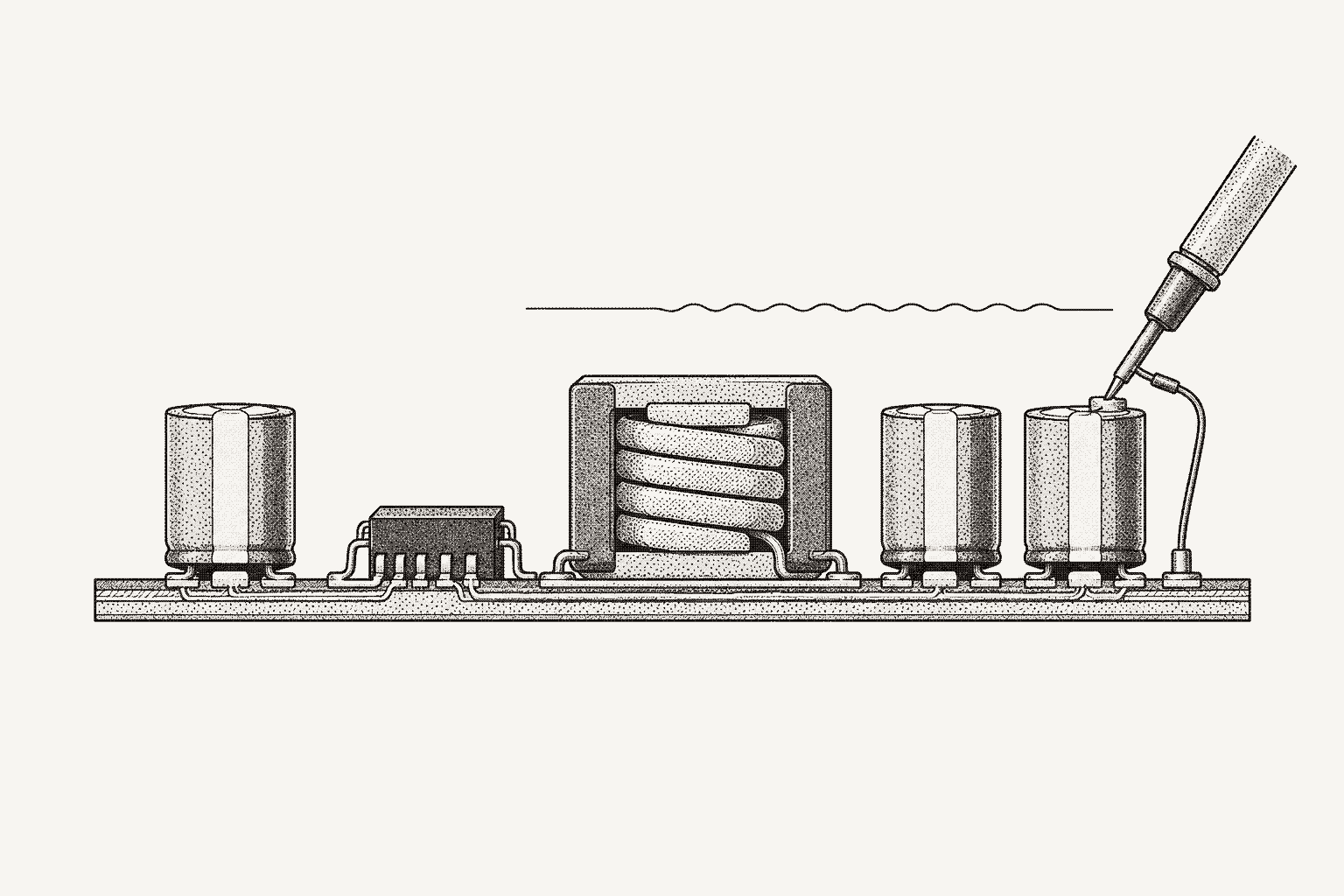
A power rail validation test plan lists every rail on the board and the tests that prove it: line and load regulation, ripple and noise, load-step transient response, startup and sequencing, efficiency, and overcurrent and overvoltage protection. Each test names its setup, instruments, limit source and pass criterion. The template below puts all of them in one table.
The column that matters most is the limit source: a limit with no source cannot be defended in a design review. For first power-on, use the board bring-up checklist; for the regulator design itself, see DC-DC converter validation.
What goes in a power rail inventory?
Start from the schematic. Every limit follows from what a rail feeds and what those consumers tolerate.
| Field | What to record | Where it comes from |
|---|---|---|
| Rail and source | Net name, nominal voltage, regulator part, topology | Schematic, BOM |
| Operating window | Minimum and maximum voltage at the consumer pins | Consumer recommended operating conditions |
| Load | Maximum current, largest step and its slew rate | Consumer datasheets, system spec |
| Sequencing | Enable source, power-good target, required order and ramp time | Consumer power-on requirements |
| Input range | Minimum, nominal and maximum input voltage | Upstream rail or system spec |
| Measurement points | Test points at the regulator and at the farthest consumer | Layout |
| Absolute maximum | Lowest absolute maximum rating among the consumers | Consumer datasheets |
TI's AN-1677 FPGA power reference design gives these entries for a Xilinx Virtex-5: a 1.0 V ±5% core rail (VCCINT), a 2.5 V ±5% auxiliary rail, a recommended power-on order of VCCINT, VCCAUX, then VCCO, and a ramp time of 0.2 ms to 50 ms, measured from 10% to 90% of nominal. Each becomes a pass criterion below; take yours from your consumers' current datasheets. From schematic to test plan and KiCad netlist test points cover extracting the inventory.
The power rail validation test plan template
Copy this table once per rail and run the protection rows last.
| Test | Setup | Instruments | Limit source | Pass criterion |
|---|---|---|---|---|
| Line regulation | Load at minimum, then maximum; step input minimum to maximum; sense output at the consumer | DC supply, electronic load, 6.5-digit DMM | Consumer window; regulator line regulation | Output in window; regulation within datasheet figure |
| Load regulation | Input at nominal, minimum, maximum; step load minimum to maximum | Same | Consumer window; regulator load regulation | Output in window; regulation within datasheet figure |
| Ripple and noise | Maximum and light load; tip-and-barrel probe at capacitor and consumer; 1 MΩ, AC coupled, the limit's bandwidth (TI EVMs: 20 MHz) | Oscilloscope, passive probe with ground spring | Consumer ripple tolerance; regulator ripple spec | Peak-to-peak below limit |
| Load-step transient | Specified step at specified slew rate; capture both edges at the consumer | Electronic load or MOSFET stepper; oscilloscope | System load-step spec; consumer window | Deviation in window on both edges; recovery in time; slew rate at spec |
| Startup and sequencing | Input and load corners; all rails, enables and power-good in one capture; many cycles | Multichannel oscilloscope; current probe on input | Consumer power-on order and ramp time | Order, delays, ramp in range; monotonic; overshoot and inrush in limits |
| Efficiency | Input corners; light to full load; input and output measured together at board test points | DMMs or power analyzer; electronic load | System power and thermal budget | Efficiency at target; dissipation within budget |
| Overcurrent protection | Ramp load past maximum until trip; then short the output | Electronic load, oscilloscope, current probe | Regulator current limit and fault mode | Trip above maximum load plus transient margin; recovery as designed |
| Overvoltage protection | Dedicated board; back-drive the output through a current-limited supply | DC supply, oscilloscope | Regulator OVP threshold; consumer absolute maximum | Protection acts below the lowest absolute maximum |
How do you measure line and load regulation?
TI's Understanding the Terms and Definitions of LDO Voltage Regulators (SLVA079) defines line regulation as ΔVo/ΔVi and load regulation as ΔVo/ΔIo, and calls both steady-state parameters: read them after the output settles. The transition itself is the load-step test.
The TPS549A20 evaluation module user's guide shows the bench procedure: one DMM on the board's input test points, a second on its output test points, the load varied from 0 to 10 A and the input from 8 to 14 V. Its table quotes line regulation as 0.2% over a 5 to 14 V input and load regulation as 0.5% from 0 to 8 A, both typical. Those are percentages over a range rather than slopes, so compute both forms.
- Sense where the limit applies. The window applies at the consumer's pins. A reading at the regulator misses plane drop, which grows with load.
- Read the input at the board. A supply's display reads at its terminals, before cable drop. Use remote sense or a second DMM.
- Settle, then integrate. Let the output and the regulator's temperature settle, and use a long integration time, such as 10 power-line cycles, so ripple averages out of the DC reading.
Report the regulation figure, to compare with the regulator datasheet, and the worst deviation from nominal, which decides pass or fail. If the regulator supports margining, also run functional tests with the rail at each edge of the window. On first silicon, the same idea becomes a voltage corner sweep; see post-silicon validation bench automation.
from dataclasses import dataclass
from typing import Callable


@dataclass
class Point:
    vin: float   # V, sensed at the board input
    iin: float   # A
    vout: float  # V, sensed at the consumer test point
    iout: float  # A


def regulation(points: list[Point], x: Callable[[Point], float], nominal: float):
    """Endpoint slope dVout/dx, change over the sweep in % of nominal, worst deviation in %."""
    pts = sorted(points, key=x)
    slope = (pts[-1].vout - pts[0].vout) / (x(pts[-1]) - x(pts[0]))
    change_pct = abs(pts[-1].vout - pts[0].vout) / nominal * 100
    worst_pct = max(abs(p.vout - nominal) for p in pts) / nominal * 100
    return slope, change_pct, worst_pct


def efficiency(p: Point) -> float:
    return (p.vout * p.iout) / (p.vin * p.iin)


def dissipation_w(p: Point) -> float:
    return p.vin * p.iin - p.vout * p.iout


# line regulation: slope in V/V; load regulation: slope in V/A (ohms)
# line = regulation(vin_sweep, lambda p: p.vin, nominal=1.0)
# load = regulation(load_sweep, lambda p: p.iout, nominal=1.0)
How do you measure ripple and noise on a power rail?
Ripple is periodic variation at the switching frequency; noise adds switching-edge spikes and broadband noise. A ripple limit means nothing without its measurement bandwidth.
The TPS549A20 guide sets the oscilloscope to "1-MΩ impedance, 20-MHz bandwidth, AC coupling," as does the TPS51113 guide. It puts the probe tip in the output test point with the ground barrel held on a ground test point, and warns that "using a leaded ground connection can induce additional noise due to the large ground loop." It quotes 10 mVpp typical ripple at 12 V in and 8 A out in forced continuous conduction mode (FCCM), though a jumper also offers auto-skip mode: a ripple number carries its operating conditions too.
- Match the limit's bandwidth. If the limit is specified at 20 MHz, measure at 20 MHz. For a PLL, ADC reference or RF supply, also capture at full bandwidth and record both.
- Remove the ground lead. Use the barrel, a ground spring or a short soldered coax pigtail. A clip lead's loop picks up the converter's field.
- Measure the floor. Touch the probe tip to its own ground at the same spot. Whatever appears is pickup, not ripple.
- Test light load in the shipping mode. Converters that change mode at light load change ripple frequency and amplitude with it.
- Probe at two points: the output capacitor and the consumer.
How do you test load transient response?
TI's Load transient testing with high slew rates lists what a transient spec typically contains: the step size, the minimum load during the event (sometimes zero), the slew rate in amperes per microsecond, the maximum deviation on both edges, and the recovery time. A test that does not reproduce all five does not test the spec.
Slew rate is where bench setups fall short. TI's Power Tips article on fast transient loads notes that an electronic load "is easily configurable to sink current in the 2-10A/us range," which suits a 3.3 V or 5 V system rail, but "core voltages can require slew rates two orders of magnitude above these levels." A major obstacle is inductance in the load path: the article calculates a maximum of 3 nH to slew 15 A at 300 A/µs on a 0.9 V output, and a 1-inch piece of 16-gauge wire looped through a current probe adds 20 nH.
Its alternative is a fast MOSFET and low-inductance sense resistor soldered from the output plane to ground, the gate pulsed by a function generator at 10% duty cycle and 1 kHz to limit dissipation. The slew-rate article calls this a FET slammer: high slew rate, but control, repeatability and current measurement are harder. Electronic load automation covers the slower end.
Record the measured slew rate, not the set value: a step slower than specified makes a marginal regulator look good.
How do you validate power supply sequencing?
TI's FPGA Power Made Simple: Sequencing summarizes the usual requirements: supplies turn on in a set order, typically core first on and first off; the rise must be monotonic, "a continual rise in output voltage"; and "typically, all rails need to get to 95% within 40 or 50ms." The exact order and timing come from the consumer's datasheet, as in the Virtex-5 example.
Capture every rail, enable and power-good in one acquisition, triggered on the input, and check:
- Order, delay and ramp time against the consumer's requirement, using the datasheet's ramp definition (AN-1677 uses 10% to 90%).
- Monotonic rise, with no dips, plateaus or reversals.
- Overshoot at the top of the ramp, inside the window.
- Power-good asserting only after the rail is in regulation.
- Inrush current against the upstream supply, fuse or hot-swap limit.
- Power-down order, if specified. The same TI article notes that chaining power-good into the next enable "cannot support a power-down sequence," so measure it.
Startup faults are often intermittent, so repeat over corners and many power cycles.
How do you measure power supply efficiency?
Efficiency is (Vout × Iout) / (Vin × Iin). Measure all four at each load point at the same time, with voltages sensed at the board's test points as in TI's evaluation module setup, so cable drop is not counted as converter loss. Sweep the load at minimum, nominal and maximum input, and let each point settle thermally.
Current measurement dominates the error at light load, so check the electronic load's readback accuracy at the low end of its range or measure current with DMMs. A datasheet efficiency curve was measured on the vendor's board with the vendor's inductor; treat it as a sanity check. The limit comes from the system power and thermal budgets, because input minus output power is heat the board must shed. AN-1677 reports both for its three rails together at full load: 90.5% efficiency, 27 W out and 2.85 W dissipated.
How do you test overcurrent and overvoltage protection?
Overcurrent. Ramp the load slowly past the rated maximum until the output trips, and record the trip current. Datasheet current-limit ranges are often wide; check that the minimum sits above your maximum load plus the largest transient, or the rail will trip in normal use. If the limit is specified as peak or valley inductor current, convert it to output current using the inductor ripple first. Then short the output and capture input current, output and neighboring rails. Confirm the fault response the datasheet describes (hiccup, latch-off or foldback), recovery once the short is removed, and that neighboring rails and their consumers stay up.
Overvoltage. Overvoltage protection exists for a regulator that loses control of its output, so simulate that: back-drive the output above the threshold through a current-limited supply. Opening the top feedback resistor also drives the output high, but an OVP comparator that senses the FB pin will not see it. The rail passes when protection acts before the output reaches the lowest absolute maximum among its consumers.
Where should each limit come from?
A limit is a claim about the design, so a reviewer must be able to trace it. Use this order and record the document, revision and table for each:
- The consumers. Recommended operating conditions at the pins of the ICs on the rail. This decides whether the product works.
- The regulator. What its datasheet guarantees. Testing against it catches a wrong part, a wrong feedback resistor or a layout problem.
- The system. Power and thermal budgets, load-step specs and applicable standards, such as ISO 16750-2 for automotive electronics.
The window is shared. A consumer's window must hold the DC setpoint error, regulation, ripple and transient deviation at once. SLVA079 builds a regulator's overall accuracy from line and load regulation, reference drift, error amplifier drift, feedback resistor tolerance and temperature coefficient. A rail can pass each row against the full window and still violate it when ripple rides on a load-step dip at low input. Split the window into a per-row budget, or check the combined worst case at the consumer.
State the decision rule. Near a limit, instrument accuracy decides the verdict. Subtract measurement uncertainty from the limit as a guard band, or write down how marginal results are handled.
How do you automate a power supply validation test plan?
Most rows are one loop: set input, set load, wait, measure, compare. SCPI instrument automation with Python builds that loop. Probe placement and fault-injection wiring stay hands-on.
Galois is agent-driven test engineering for hardware teams: agents generate tests and instrument drivers, run them on real benches through the open-source galois-edge daemon, and turn the results into reports and a shared engineering record.
A Galois test is a sequence: versioned YAML whose steps call named commands from each instrument's profile in the instrument library and judge results against explicit limits. A shortened illustration of the load regulation row for the Virtex-5 core rail:
name: "VCCINT load regulation, nominal input"
steps:
  - name: "Set input to 5 V"
    type: action
    config:
      instrument_id: "psu"
      command_name: "source_voltage"
      parameters: { value: "5.0" }

  - name: "Enable input"
    type: action
    config:
      instrument_id: "psu"
      command_name: "output_on"

  # eload commands as named in the B&K Precision 8600 profile
  - name: "Load to constant current"
    type: action
    config:
      instrument_id: "eload"
      command_name: "function"
      parameters: { mode: "CURRent" }

  # load points: AN-1677 rates its core channel at 3 A; take yours from the rail inventory
  - name: "Load at minimum"
    type: action
    config:
      instrument_id: "eload"
      command_name: "current_level"
      parameters: { value: "0.5" }

  - name: "Enable load input"
    type: action
    config:
      instrument_id: "eload"
      command_name: "input_state"
      parameters: { state: "ON" }

  - name: "Settle"
    type: wait
    config: { duration_ms: 2000 }

  # limit source: consumer recommended operating conditions, 1.0 V +/-5%
  - name: "VCCINT at minimum load"
    type: numeric_limit
    config:
      instrument_id: "dmm"
      command_name: "measure_voltage_dc"
      low_limit: 0.95
      high_limit: 1.05
      unit: "V"
      comparison: "GELE"

  - name: "Load at maximum"
    type: action
    config:
      instrument_id: "eload"
      command_name: "current_level"
      parameters: { value: "3.0" }

  - name: "Settle"
    type: wait
    config: { duration_ms: 2000 }

  - name: "VCCINT at maximum load"
    type: numeric_limit
    config:
      instrument_id: "dmm"
      command_name: "measure_voltage_dc"
      low_limit: 0.95
      high_limit: 1.05
      unit: "V"
      comparison: "GELE"

  # end state, reverse of power-up: load input off, then supply output off
  - name: "Disable load input"
    type: action
    config:
      instrument_id: "eload"
      command_name: "input_state"
      parameters: { state: "OFF" }

  - name: "Disable input"
    type: action
    config:
      instrument_id: "psu"
      command_name: "output_off"
GELE means low ≤ value ≤ high, so both boundaries pass; the budget and guard band above would narrow the window. Every run stores, per step, the SCPI sent, the raw response, the measured value, the limits and the instrument, with operator and DUT serial: the raw material for a DVT test report.
An agent-drafted sequence cannot run until an engineer approves it; reviewing an AI-generated test plan has a checklist. The agent walkthrough below takes these regulation rows from a plain-English objective to a report.
For protection rows, profiles give command parameters types and ranges, so out-of-range values are rejected before reaching the instrument, and a profile can mark commands that can damage hardware as dangerous. AI test automation for hardware benches and LLM instrument safety cover those layers; the product overview shows the app.
How do you run power rail validation in Galois with Évariste?
Évariste, the agent in the Galois platform, drafts the same regulation rows as a sequence from a plain-English objective and runs it once you approve. Open it from the app sidebar (Ctrl+Shift+E) beside the project, on Galois Cloud, a dedicated cloud or an on-prem deployment; it reaches the bench through galois-edge.
Instruments. Ask "List connected instruments" to confirm the DC supply, the B&K Precision 8600 load and both DMMs are connected, and read the commands in each profile. For a load or supply outside the library, upload its programming manual; Évariste generates a profile and, after you review it (the current-level range and the input-on flag first), deploys it to the edge and binds it.
Objective. State the points and limit with its source, as the template row does:
Create a power rail validation sequence for VCCINT, the Virtex-5 core rail: line and load regulation. Input at 4.75, 5.0 and 5.25 V from the DC supply. At each input, the B&K 8600 in constant current at 0.5 A, then 3.0 A, settling 2 s. Measure VCCINT on the 6.5-digit DMM at the FPGA test point, limit 0.95 to 1.05 V (1.0 V ±5%, consumer recommended operating conditions), and record the input at the board test points on a second DMM. Finish with the load input off, then the supply output off.
The input corners assume a 5 V ±5% upstream rail; use your inventory's.
Draft. Évariste writes the six points as a draft in the format above: a numeric_limit step for VCCINT at every point and a measure step, which records without judging, for the board input. The minimum-input, maximum-load corner:
name: "VCCINT line and load regulation"
steps:
  # setup as in the sequence above, with the input set to 4.75 V before
  # the supply output turns on; then the 0.5 A point at 4.75 V
  - name: "Load 3.0 A at 4.75 V input"
    type: action
    config:
      instrument_id: "eload"
      command_name: "current_level"
      parameters: { value: "3.0" }

  - name: "Settle at 4.75 V, 3.0 A"
    type: wait
    config: { duration_ms: 2000 }

  - name: "Board input at 4.75 V, 3.0 A"
    type: measure
    config:
      instrument_id: "dmm_in"
      command_name: "measure_voltage_dc"
      unit: "V"

  # limit source: consumer recommended operating conditions, 1.0 V +/-5%
  - name: "VCCINT at 4.75 V, 3.0 A"
    type: numeric_limit
    config:
      instrument_id: "dmm"
      command_name: "measure_voltage_dc"
      low_limit: 0.95
      high_limit: 1.05
      unit: "V"
      comparison: "GELE"

  # the same two points at 5.0 V and 5.25 V; closing steps turn
  # the load input off, then the supply output
Review and approval. Check each limit against its source, the point order, the 2 s settle time, and that every level is set before its output turns on and the shutdown runs in reverse, then approve the draft. How to review an AI-generated test plan has the checklist. Every edit, in conversation or the sequence builder, is a new version with history and a diff, and a settled sequence can be production-locked. A command a profile marks as dangerous, sent on its own from the conversation, waits for your confirmation before Évariste sends it.
Run and results. Start the run; galois-edge executes it while Monitor shows channels live, so you can see whether VCCINT has settled before each 3.0 A reading. Every step records its measured value, limits, pass or fail, raw command and response, instrument, operator, DUT serial and timestamps. Then ask Évariste which VCCINT points passed closest to 0.95 or 1.05 V, what line and load regulation come to in the slope and percent-of-nominal forms regulation() returns, and how this board's run compares with the previous build's. Check its figures against the recorded steps.
Report. Ask it to "Generate a test report from the last run" as PDF or HTML, edit it in the report editor, and share the results to Slack. Other rows start the same way, with their own setup and limits from the template: "Measure output ripple at full load" or "Run an efficiency test across input voltage range".
You no longer write or maintain the instrument wrappers, the corner loop, retry and error handling, logging, CSV wrangling or a report script. The points and limits from the consumer and regulator datasheets, review and approval, probe and sense placement, fault-injection wiring and bench safety stay with you.
| Step | Code path (this guide) | Galois with Évariste |
|---|---|---|
| Connect | PyVISA sessions and drivers from the Python guide | "List connected instruments"; library or generated profile |
| Define points and limits | Input and load lists; window in code | Corners, loads and 0.95 to 1.05 V in plain English |
| Build the sequence | Hand-written loop or YAML | Drafted sequence; versioned edits |
| Review | Code review | Engineer approves the draft before it runs |
| Run | Script on the bench PC | Run through galois-edge; Monitor live |
| Record | Your logging and CSV | Per-step value, limits, raw response, operator, DUT serial |
| Interpret | regulation() in rail_metrics.py | Near-limit points, regulation figures, run comparison |
| Report | Your report script or DVT template | Generated report; report editor; Slack |
Whatever runs the plan, keep the template's shape: one row per test, a named source for every limit, a recorded result for every point. EVT, DVT and PVT testing covers where these rows fit across builds.
Frequently asked questions
- What is the difference between line regulation and load regulation?
- Line regulation is the change in output voltage for a change in input voltage at a fixed load (ΔVout/ΔVin). Load regulation is the change in output voltage for a change in load current at a fixed input (ΔVout/ΔIout). Both are steady-state parameters: read them after the output settles. The behavior during the change itself is the load-step transient test.
- How do you test overcurrent protection on a power rail?
- Ramp the load slowly past the rated maximum until the output trips, and record the trip current. The minimum of the datasheet's current-limit range should sit above the maximum load plus the largest transient, or the rail will trip in normal use. Then short the output and confirm the fault response the datasheet describes (hiccup, latch-off or foldback), recovery once the short is removed, and that neighboring rails stay up. Run it last, on a dedicated board.
- Why is my electronic load too slow for load transient testing?
- Wiring inductance and the load's own slew limit. TI notes that an electronic load easily handles 2 to 10 A/µs, enough for 3.3 V or 5 V system rails, while processor and FPGA core rails can need slew rates two orders of magnitude higher. For those, solder a MOSFET and low-inductance sense resistor across the output and drive the gate from a function generator.
- Where should pass/fail limits in a power validation plan come from?
- From the consumers first: the recommended operating conditions of the ICs on the rail, at their pins. Then the regulator datasheet, which says what the part guarantees, and then system requirements such as power and thermal budgets and load-step specs. Record the document, revision and table for every limit so a reviewer can trace it.
- Can I run a power rail validation plan without writing Python?
- Yes. Évariste, the agent in the Galois platform, drafts a row such as line and load regulation as a versioned sequence from a plain-English objective with your input corners, load points and limits, and you review and approve it before it runs on the bench through galois-edge. Every step's measured value, limits and raw response are recorded, and Évariste can find the points nearest a limit and generate the test report from the run. Probe placement, fault-injection wiring and bench safety stay with you.
Bring Galois to your bench.
The daemon is Apache-2.0, free forever. Enterprise runs in your cloud or on-prem.